Air filter
Captures debris before it coats the evaporator or blower. A filter affects airflow but does not create cooling.
 608 Study Buddy
Interactive Indoor Component Lab
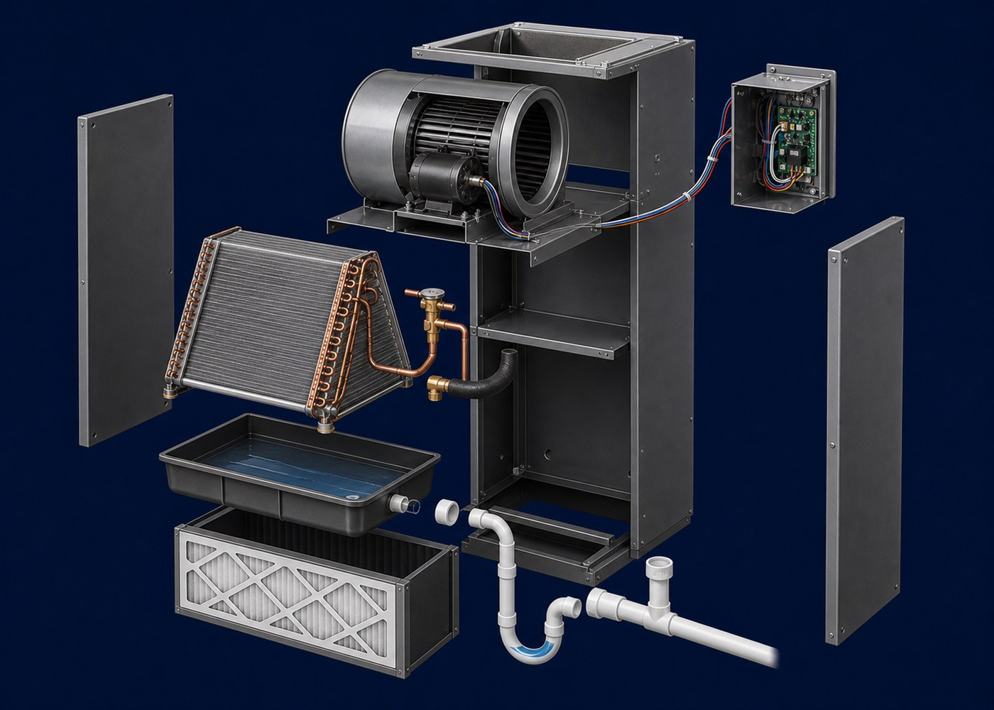
Open the indoor cabinet, separate the major assemblies, and follow three different things: moving air, evaporating refrigerant, and water leaving through the condensate drain.
Safety: Exam-prep material, not service instructions. Refrigerant work involves high pressure, electrical, burn, frostbite, and asphyxiation hazards. Follow the equipment manufacturer’s instructions, applicable codes, and your training. Terms
Filter, cool, dehumidify, drain
The filter protects the coil and blower from debris. It does not remove heat or moisture by itself.
Use the numbered steps or play the teardown. Each part travels directly to the matching position in the final exploded image.
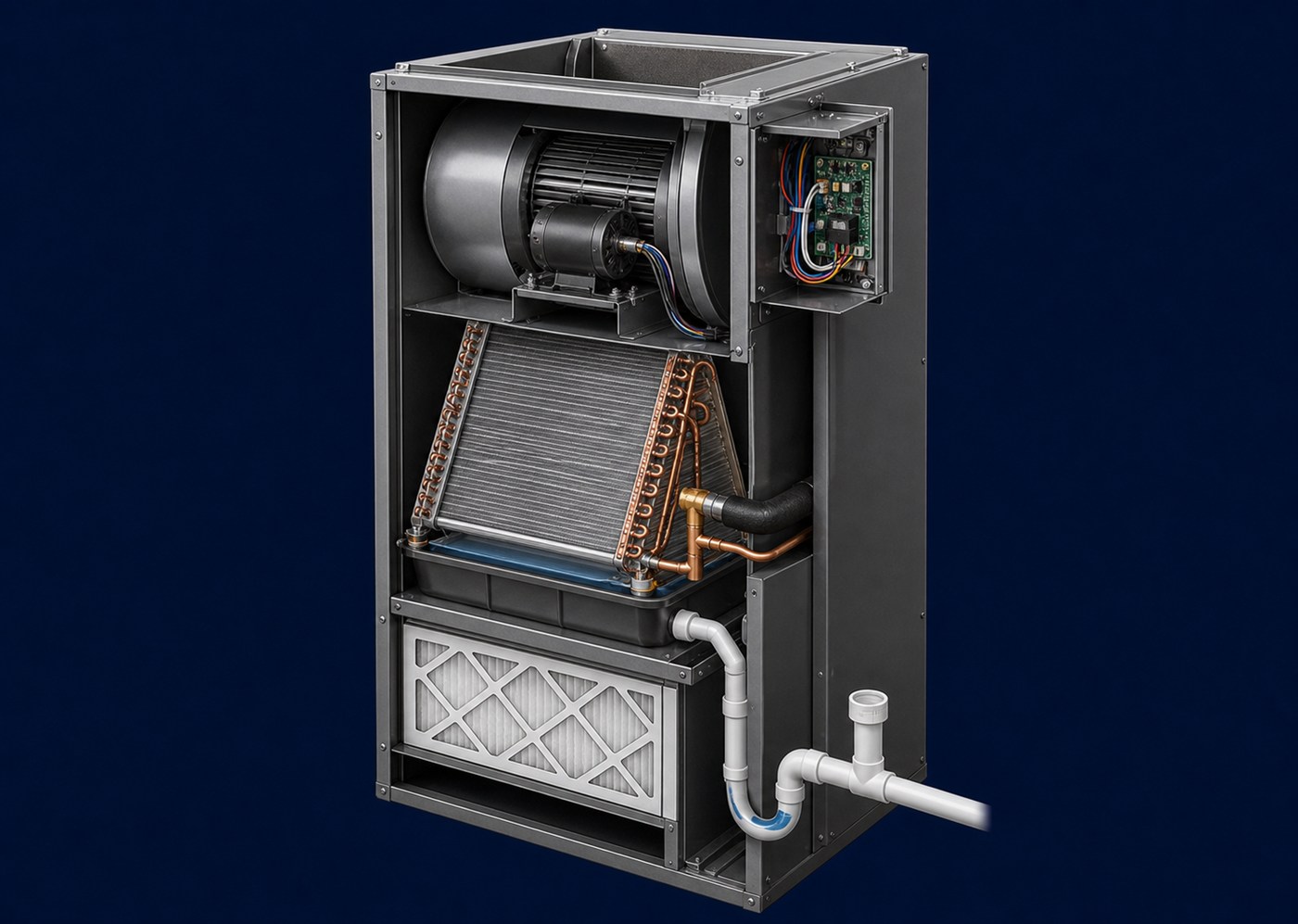
Cutaway view: a representative upflow draw-through air handler with the blower downstream of the evaporator coil.
Moisture can also condense on the cold fins. That water is separate from the sealed refrigerant circuit and must fall into the drain pan.
Name the assembly correctly
The evaporator coil is the refrigerant-to-air heat exchanger. The air handler is the indoor cabinet assembly that can include the coil, blower, filter rack, controls, drain pan, condensate connections, and optional electric heat. This model omits optional heat strips so the cooling path stays clear.
Warm return air enters at the bottom, passes through the filter, and crosses the cold evaporator coil. Low-pressure refrigerant inside that coil absorbs heat and boils. The downstream blower then sends the cooler air through the top supply opening and into the duct system. This arrangement is called draw-through because the blower pulls air across the coil.
The indoor coil also dehumidifies whenever its surface is below the air's dew point. Water vapor from the air condenses on the fins, drips into the pan, and leaves through the condensate drain. That water is not refrigerant and the PVC drain is not connected to the sealed copper refrigerant circuit.
| Point to trace | What is moving | Typical condition | What happens next |
|---|---|---|---|
| Bottom return / filter | Indoor air | Warm and possibly humid | Crosses the evaporator coil |
| Metering-device outlet | Refrigerant | Low-pressure liquid-vapor mixture | Enters the evaporator |
| Evaporator outlet / suction line | Refrigerant | Low-pressure vapor, normally superheated | Returns to the outdoor compressor |
| Coil surface to drain pan | Condensed water | Liquid water removed from air | Leaves through the primary drain |
| Top supply opening | Indoor air | Cooler and usually drier | Enters the supply ductwork |
Captures debris before it coats the evaporator or blower. A filter affects airflow but does not create cooling.
Absorbs heat into low-pressure refrigerant. Its cold surface can also condense moisture from indoor air.
Creates the pressure drop and controls refrigerant entering the evaporator. The pressure does not drop merely because the liquid line reaches the indoor cabinet.
Moves return air across the filter and coil, then pushes conditioned air into supply ductwork. Air does not flow through the refrigerant tubing.
Operate and protect the blower and other electrical loads. Exact boards, relays, and optional heat controls vary by equipment.
Collect water removed from humid air and carry it away. The primary and secondary openings are different from the copper suction and liquid lines.
Follow the water
In this representative draw-through layout, the blower is downstream of the coil. That puts the drain-pan connection under negative pressure while the blower runs. A correctly sized trap allows water to drain instead of air being pulled backward through the pipe.
The illustration also shows a vent/cleanout after the trap and a continuing downward slope. Trap dimensions, vent position, insulation, secondary drainage, termination, and permitted connections are installation-specific: follow the current manufacturer instructions and local code.
Complete the split system
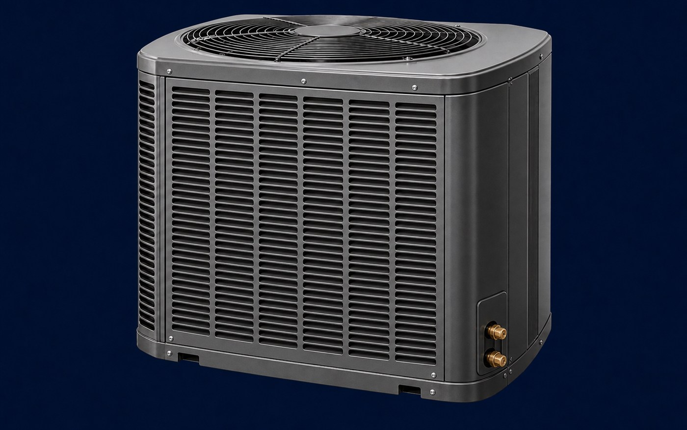
The indoor side absorbs heat and removes moisture. The outdoor side raises refrigerant pressure and rejects that heat to outdoor air.
Open the outdoor Component LabIndependent study material; not affiliated with or endorsed by the EPA. This model is for concept learning only and does not replace manufacturer instructions, codes, training, electrical safety, PPE, or proper condensate and refrigerant service practices.